
Written by: Andres Cuenca
Objective:
This post shares insight to an user to build his/her own garden automation project. This is a fun project for those who are interested on building their own indoor smart garden project that is program to nurse vegetables or any desire plants. The time, dedication and patience to grow vegetables at home requires the user to provide an adequate nursery to the plants. However for those who don’t have time can build this project to grow vegetables or plants at home.
Background
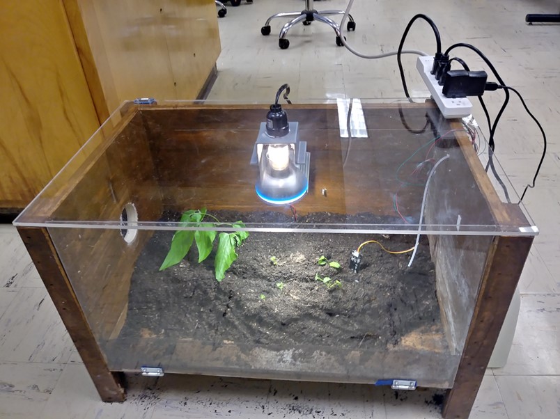
The automated greenhouse makes it possible to replicate a certain temperature and water irrigation to consequently grow food. Also, making the greenhouse automated enables people to grow their own food at home without constantly checking the status of the plant. The automated greenhouse is intended to be for indoor use.
The enclosure of then greenhouse has dimensions of 24”x18”x18”, which is a great size for placing anywhere the house.
Flow-Chart
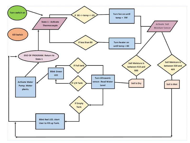
For this project, considering variables such as reading moisture and temperature values from sensors, reading water level from the reservoir, providing a heating and cooling system to the greenhouse, and alerting the user when to fill up the tank were heavily taken in consideration by the team. Therefore, the best method to incorporate all these variables was applying a finite state-machine algorithm. The finite state-machine will perform transitions based on an output or input data that are collected by the electronic devices and transferred to the Arduino. Our algorithm follows a path of logic, where each state analyzes a condition. The state-machine initializes the program to read the temperature values. If the temperature of the greenhouse is too cold, activate the heater, if it’s too hot, activate the fan. Once the thermometer reads a value of 80F, then the system proceeds on checking the moisture of the soil. If the soil is dry, then check the water level of the tank. If there’s enough volume of water inside the reservoir, then activate the water pump to water the plants. If the soil is wet, then cycle to the first state tp read the temperature of the greenhouse. Below a flowchart provides a clear visualize of the logic setup for the automation.
Circuit Layout
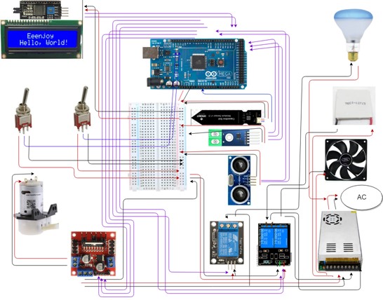
The wiring schematic above reflects all the components used in this project from sensors to actuators and the controller. Switches, motor driver, moisture sensor, temperature sensor, ultrasonic sensor , are all connected to digital pins in the Arduino Mega. On the other hand, the LCD is connect to the analog pins in the controller. The fan and light bulb are indirectly powered by a 12V Power Supply.
Circuit Connections
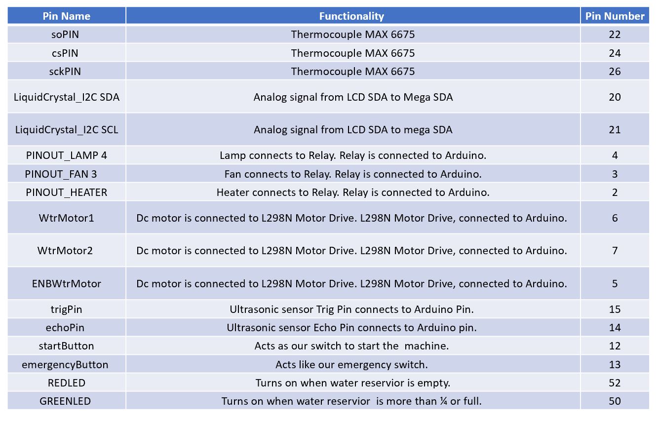
Below are proper connection table for the electronics and sensors to the Mega Arduino microcontroller.
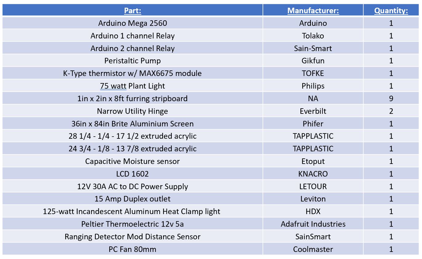
Bill of Materials
Below is a list of materials to help a user get started. Most of these items can be found off the shelf or can be ordered through Amazon.
Program Code
Interested for the open-source codes? Check out my Github Page!