Written by: Andres Cuenca
Introduction
Working on a DC motor integrated with a quadrature encoder can be used for reading the angular position, velocity and acceleration data of the motors shaft. The quadrature encoder is a great feedback sensor that can be integrated to a PID controller system and be applied to robotics, drones, RC cars, or any moving mechanism.
Materials for this project
For this project the following materials were purchased
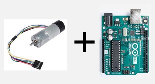
- 1 Arduino Uno Microcontroller
- 1 DC Motor with quadrature encoder
- 1 L298N H-Bridge (motor driver)
- 1 Breadboard
- 1 12V Power Supply
- some wires for proper connection
- Also, used an Arduino IDE to compile and test code (more to that later)
Background on Quadrature Encoders
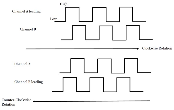
The quadrature encoder is placed inside the DC motor and used for obtaining feedback to read the angular position, velocity and acceleration of the shaft of the motor. Two optical sensors create rectangular pulses measured in 90 degrees phase difference. There are two channels, A and B that can be applied for counting each pulse to determine the direction of the shaft of the motor. The following flow chart below is derived behind this concept.
Flowchart of Quadrature Encoder
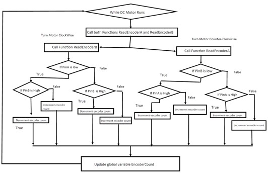
This flowchart provides a reference on how to determine the logic setup to establish the direction rotation of the DC motor shaft. In order to determine the rotation direction, a global variable is applied for keeping track of the rectangular pulses generated by the optical sensor. The left side of the flowchart determines that the shaft of the DC motor is rotating clockwise, which means channel A is leading channel B by 90 degrees; and vice-versa if the DC motor shaft rotates counterclockwise.
Wiring Connections
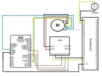
Simple Wiring Connections
- A 12V voltage supply will be directly connected to 12V and GND pins of the L298N-motor driver
- Arduino pins 6,7 and 8 will be connected to l298N motor driver pins ENA, IN1, and IN2
- 5V Arduino pin connects to the Quadrature sensor 5V pin
- DC Motor Negative Polarity is wired to L298N motor driver pin OUT2
- DC Motor Positive Polarity is wIRed to L298N motor driver pin OUT1
- Arduino pins 2 and 3 will be connected to the DC motor encoders A and B, respectively.
- DC motor GND will share common ground to the Arduino, 12V power supply and motor driver.