Written by: Andres Cuenca
Introduction
This DIY post covers on how to set up a DC motor with quadrature encoder, and compile an Arduino PID controller code, to turn the shaft of the motor to any desire setpoint value.
It’s recommended to complete the project below before jumping into the Arduino PID controller.
Reading Data from Quadrature Encoder of DC motor
Background on PID Controller
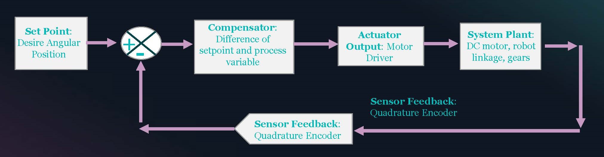
For the DC motor shaft to turn at the desire angular position, the steady-state error of the angular position should equal to zero, without experiencing any excessive overshoot, and a low settling time within a range of 15-20 seconds. To reach this goal, a PID (proportional, integral and derivative) controller code was complied on an Arduino. There are three coefficients Kp, Ki and Kd that must be properly tuned to get a correct response for the DC motor. For this task, a quadrature encoder is applied to read pulse counts from the optical sensor and the Arduino uses this information to compute the angular position and velocity. In addition, the Arduino embeds the PID controller and keeps track of the setpoint and process variables. A PID controller operates inside a closed loop system, which a diagram is shown below.
Closed Loop System Diagram
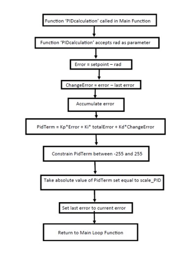
Flowchart of PID Controller
Tuning Kp, Ki and Kd variables
Often times when a DC motor is purchase a manufacture specifications sheet will have the proper coefficients for the Kp, Ki and Kd. However, when this information is not available or if a PID controller is integrated to a plant system that is derive from a electro-mechanical equations of the load and inertia acting on the DC motor, then proper tuning on the coefficients is required.
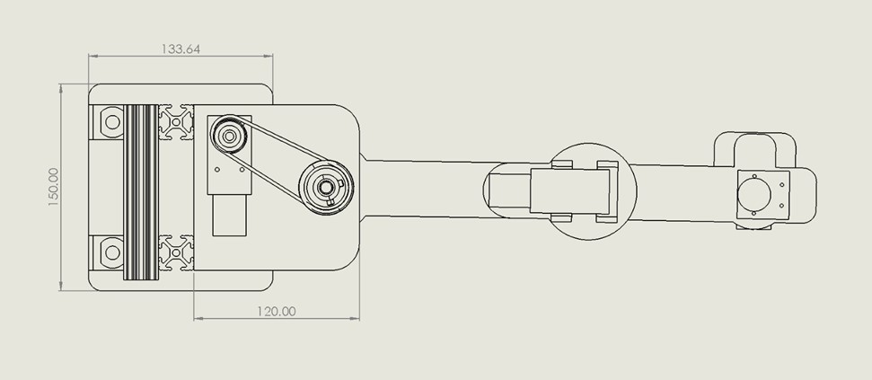
In this example, a SCARA robot was designed and dimension from scratched. Below are some drawings to illustrate how the DC motors were mounted to the robot model.
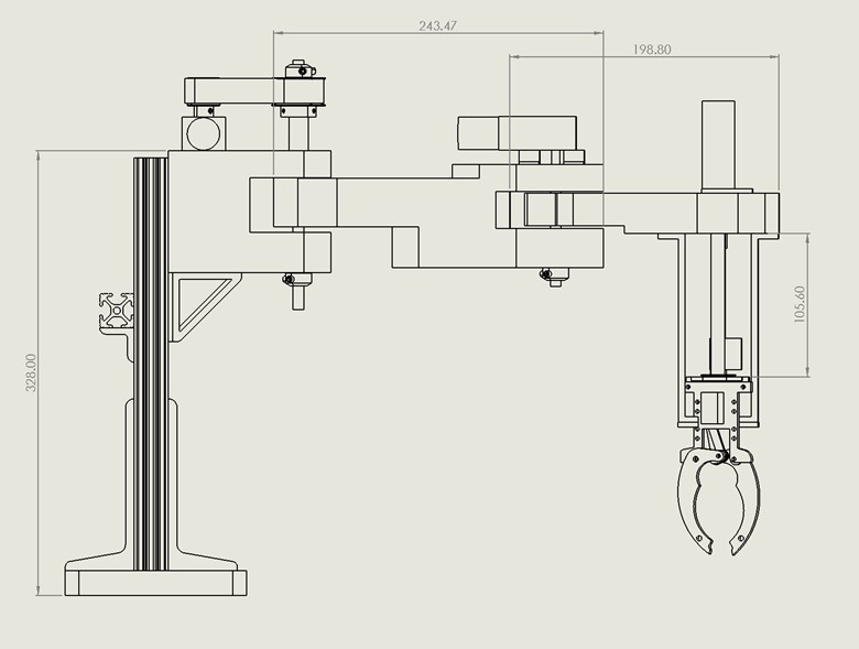
The first motor drives the first and second rotating linkages. The second motor is directly coupled to the second rotating linkage. For each case of the motor it handles different loads and inertia. This information was analyzed using SolidWorks.
Part of process of integrating the PID controller to the plant system equation is to analyze the mass and load inertia of the entire model and apply this process to find the proper tuning variables that can meet the design specifications such as achieving zero steady-state error, low rising time and low overshoot. This can be achieved using MATLAB.
MATLAB PID Script
Tuning these variable is crucial to achieve a smooth and desire angular velocity and angular position for the DC motor. It would take hours of making assumptions for properly tuning these variables. However I complied a MATLAB script that can save time and analyze step response graphs that respond to the given the electro-mechanical equations of the DC motor and robotic arm. Analyzing the step response graphs can determine the overshoot, settling-time, and achieve a steady-state error equal to zero.
MATLAB: PID Controller Simulation to Tune Motors
Once the tuning coefficients meet and satisfy the design criteria, these values can be transpose and tested on the actual hardware. Below is a complied Arduino PID code to drive the shaft of the DC motor to desire angular position.