SolidWorks CAD Models Design by Andres Cuenca
Showcasing some of most recent SolidWorks projects that I worked on! Some projects include a live demo video. Check it out!
SCARA (Selective Compliance Assembly Robot Arm)
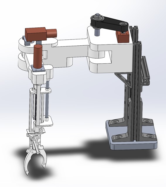
Most of the components such as the two revolute, prismatic linkages and end-effector claw can be 3D printed, making this project cost efficient for the user to build at home.
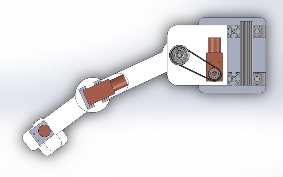
This robot is driven by DC motors coupled to one revolute joint. Another DC motor is coupled with two sized gears and one timing belt to generate more torque for the linkages to move. The DC motors are integrated with a quadrature encoder to read the angular position and velocity of the linkages.
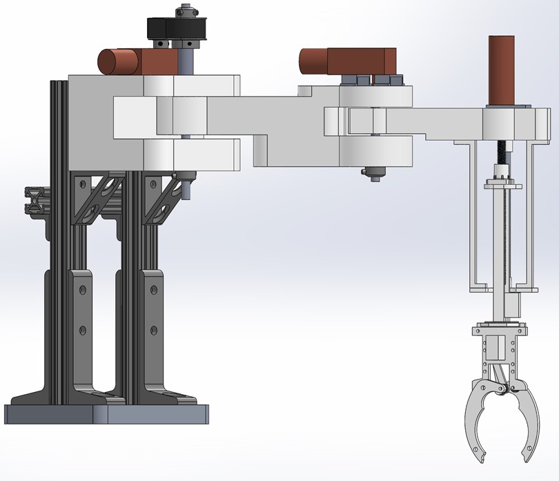
This robot’s prismatic linkage which connects to the end-effector is designed with pillow bearings, a coupler, a linear ball bushing, and a linear screw driver.
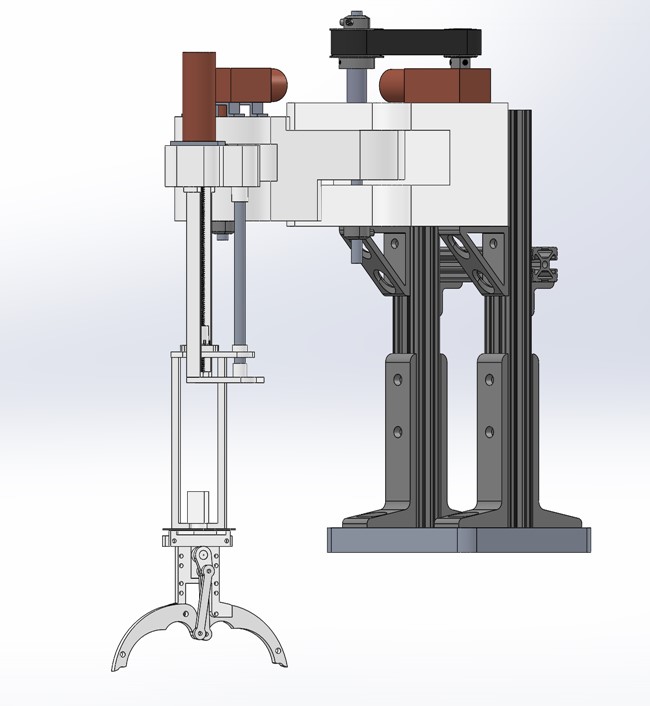
Overall dimension of the SCARA robot stands at a height of 14 inches, and extends outs to 12 inches. The dimensions of this SCARA robot is great for users to place it on a table to learn to pick and place small objects and this robot is easily portable.
PRRR (Prismatic Revolute Revolute Revolute) Robot
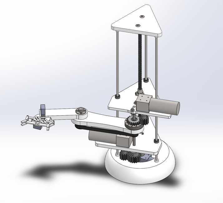
The first linkage moves in a upward and downward motion and is driven by a linear screw drive. On each steel rod, three linear ball bushing are used for to the linkage to move a smooth motion. This mechanism borrows the same concept of a linear actuator. The DC motor below provides enough rotational torque to generate enough power for the linear screw drive to push and pull the top and bottom prismatic platform.
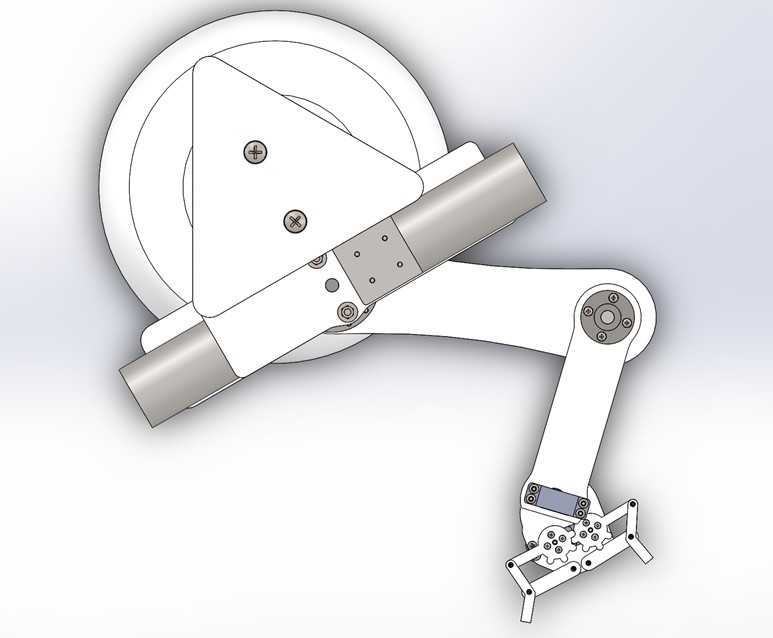
In total there are three linkages that rotates, including the end-effector which is coupled to a servo motor that is mounted at the end of the second revolute linkage.
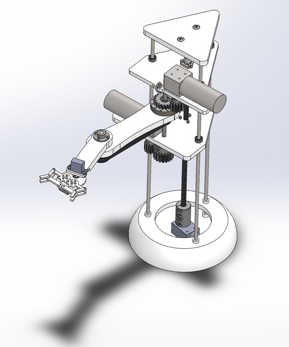
The end-effector (claw) of the robot can extend up to 10 inches. The robot stands at 18 inches tall. The robot was designed to pick and place objects from shelfs, and easily transport the objects at different accessible locations of the robot’s workspace station.
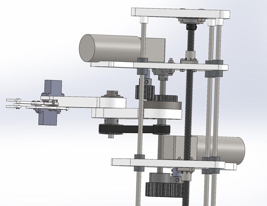
Two DC motor which are integrated with a quadrature encoder are used to read the angular position, and velocity of the rotating linkages. One DC motor is mounted to both gears, which generate sufficient torque to rotate the first rotating linkage. Another DC motor is applied for rotating another rotating linkages, which is power driven by a timing belt and pulley system.
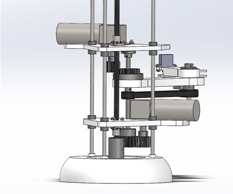
There’s five motors in total that will provide the motion, position, and velocity of each linkage. Each motor has a feedback sensor that can be used to read the final and desire position of the end-effector.
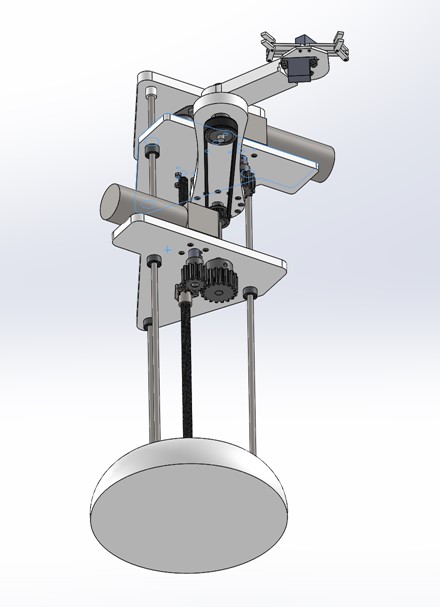
This project can be easily assembled using a 3D printer to manufacture the components. Most components can be printed using PLA material, making the project cost-efficient and reliable for users. DC motors and servo motors can be purchase on Amazon. The mechanical components such as linear screw drive, rods, couplers, linear ball bushing, rotating ball bearings, timing belt and timing pulley can be purchased at manufacturing suppliers such as Misumi or McMaster.
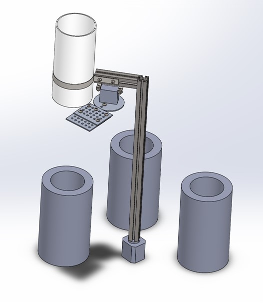
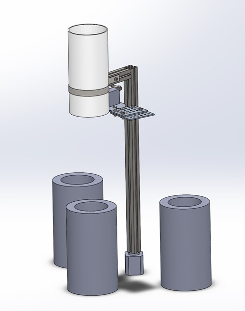
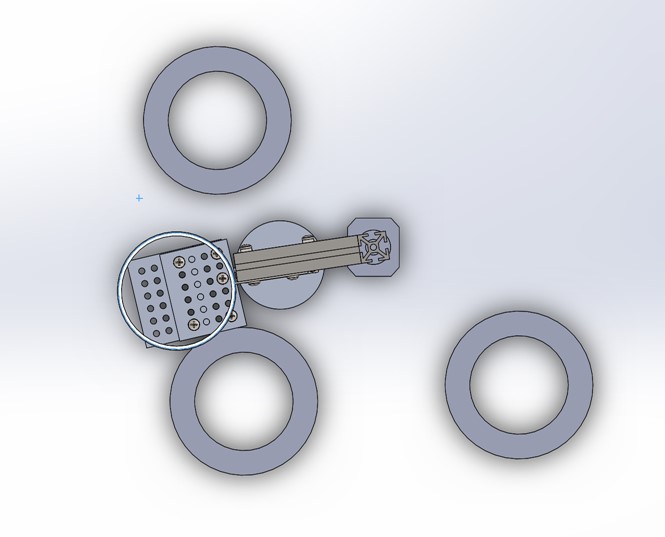
Waste Sorting Robot
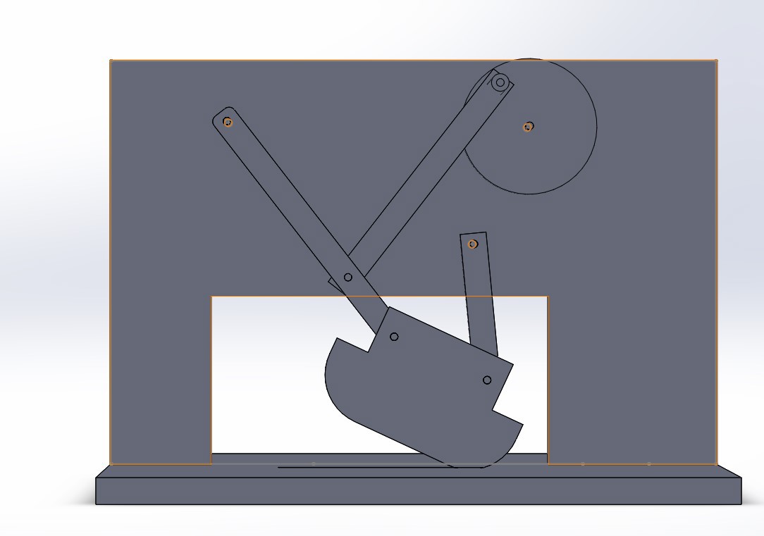
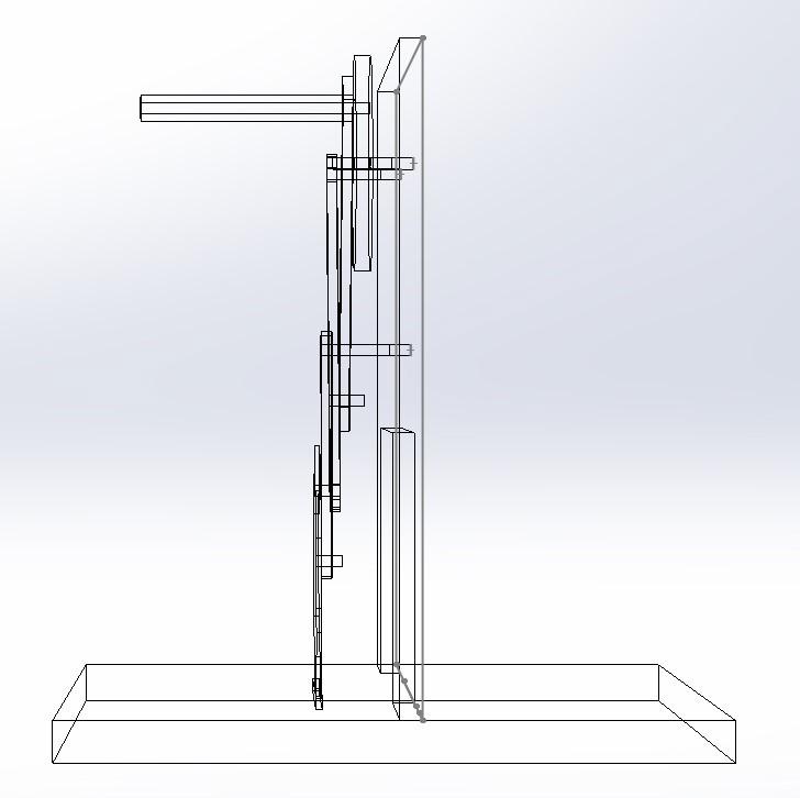
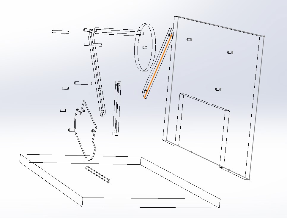
Vegetable Cutter Mechanism
